
Guitar Moded
Fender Stratocaster SSS
Description
- SSS pickup layout
- 3 single coils, direct Fender replacement pickups
- 1 volume pot with pull/push
- 1 blender pot
- 1 tone pot
- 1 Fender 5-way switch.
Medium
Features
- Provides multiple alternative combos to the original stock wiring..
- The different combinations are achieved with the use of a blender pot and a pull/push under the volume pot.
This is the original diagram found on Guitar Tech Craig.
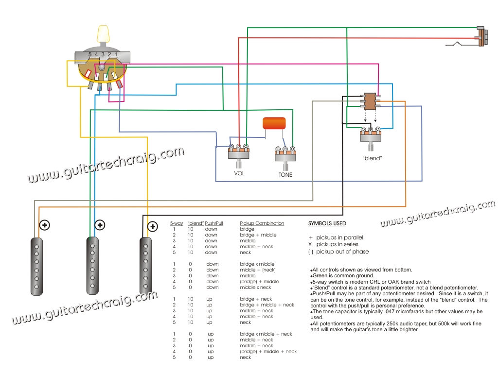
Many people tried it and didn't success. I bet that the issue is that this diagram is showing the common lugs as they would be in an old Fender switch but, current switches have their common lugs swapped.
The following diagram is my take of the original one, fixing the issue with the lugs, clarifying the design respect of grounds and jumpers.

Comments
This request was originally made during Juny 2009, were some users were interested on use the Mega Strat Wiring mod presented in Guitartechcraig and, that reported as not working.
I suspect this was the case if they didn't understand the meaning of each lug and they tried to directly solder everything as drawn. Without taking into account which lug is which, a direct soldering of this design in a modern Fender 5-way switch will lead to unexpected results because, by example, you will be wiring the hot output to the neck pickup lug, instead of the common lug, etc.
This is a very tricky design and, the major key is how the blender pot works. It's relatively easy to wire but, a clever and tricky design that, it's not easy to understand for everyone.
Just to give an example about how this wiring works. Let analyze Neck position.
So, at left, the neck pickup goes to its natural lug in the 5-way and, at right, the bridge negative goes to the middle lug of the blender pot and, the middle positive goes to the right lug of the blender. That makes a virtual link in series between both pickups, depending on the position of the blender pot.
When at zero, both pickups are connected together in series (in fact, when going from middle position to zero). When at 10, the bridge pickup is grounded and disconnected from the middle's positive (the series arrangement is broken).
And, in the right side of the pull/push, the center of the blender (negative of bridge pickup) is linked to the negative wire of the neck pickup.
So, if the pull/push is down and the blender is at zero, for neck position (position 5 in the original diagram), what we have in fact is the middle pickup in series with the bridge pickup and the neck pickup. The positive of the bridge pickup is disconnected in the 5-way for this position so, no sound middle in series with bridge.
But, the neck is connected to the hot path and the middle is always grounded so, what we have for this position is Middle in Series with Neck.
In this same case, if the blender is at 10, we are disconnecting the middle positive from the bridge negative and the bridge negative is being grounded but, since in the pull/push the bridge negative is linked to the necks negative, the neck results ground as well. Since the positive of the bridge isn't linked to the hot path in the 5-way but the neck positive is, we achieve just the neck pickup for this position.
So, blender at ten gives us neck pickup, blender at zero gives us middle in series with neck, instead.
But, what happens when the pull/push is up then?.
Now, the neck negative will be always grounded and the neck positive will be always on the hot path so, at least the neck pickup will sound always by default, if we don't do anything else to avoid it.
Remember that we still have that virtual link between the middle and bridge pickup in the blend pot so, let analyze all together and let see what happens.
Both (middle in series with bridge) pickups are unlinked of the neck pickup and, since the bridge positive isn't in the hot path, we will get no sound from those pickups, when the blender is at zero.
When the blender is at 10, the serial link is broken and the bridge pickup is being grounded but, since neither the bridge positive or the middle positive are in the hot path, we just get the neck pickup.
Let analyze the middle + neck position now (Position 4) in the original drawing.
First effect is that the bridge positive is being grounded (in the right side of the 5-way).
The bridge negative is linked to the neck negative in the pull/push, when pushed down.
This time, the middle positive is added to the hot path, together with the neck positive.
The middle positive can be also potentially linked to the bridge negative in the blender pot.
In one side, we have the neck pickup linked with the bridge pickup out-of-phase. The negative of the neck pickup is linked in the pull/push with the negative of the bridge pickup and, the positive of the bridge pickup is grounded so, we have a virtual humbucker with the bridge pickup out-of-phase.
In other side the middle pickup has it's negative grounded and the positive linked to the negative of both pickups, bridge and neck. So, what we have here is bridge out-of-phase in series with neck in parallel with middle in series with neck but, neck positive is also linked to the hot in the 5-way switch.
That shortcuts the neck pickup, removing it from the signal path and therefore, what we have is bridge-oop in parallel with middle.
When the blender is at 10, the link between middle positive and bridge negative is removed and the bridge negative is grounded. Since the bridge positive is grounded in the 5-way switch also, the bridge pickup is removed from the circuit but, since the negative is linked to the neck negative, the neck pickup is being grounded now. The middle negative is always grounded and, the positive was already added to the hot path, therefore, we have here Neck in parallel with Middle.
And when the pull/push is up?.
Neck positive is always in the hot path and the negative is grounded so, this pickup should sound as default.
Middle negative is always grounded and for this position, the positive was added to the hot path so, in principle, both pickups should be in parallel.
Bridge positive is still grounded and, the negative is virtually linked to the middle positive in the blender pot.
When the blender is at zero, the three pickups are sounding in parallel.
When the blender is at 10, the link bridge negative - middle positive is being removed and, the bridge negative is being grounded and, since the positive is also ground, the pickup is being removed from the circuit. The other two pickups continue as they were so, we have neck in parallel with middle.
To go one by one can take very long so, try to understand the basics of how the combination of that blender with the pull/push work together. Maybe, it's easier for you to think on that blender as if it was just a SPDT on/on switch.
The good thing of doing it with a blender pot is that you can reuse one of the stock tone pots for that job and the guitar still looks like it was and, between zero and 10 there are some grey zones, where you can get other nuances for each combo.
But I think it can be easier to have a toggle DPDT on/on there instead of the blender to do the job.
I was pinning away for such type of blogs, thanks for posting this for us. electrician brisbane
ReplyDeleteThanks a lot for your feedback.
DeleteIt's really comforting to know that there is someone "on the other side" and, that I can be of help to someone else.
Thanks for your interest in the wiring. The diagram linked from guitartechcraig.com has now been revised to be correct and easier to read. Please check back for new developments. I'm working on another version of this that adds a new twist to the tone options.
ReplyDeleteGuitar Tech Craig